
in today’s post, I will be explaining the very basics of logic gates. By the end of the post, you should have a good understanding of the functions of each of the most common logic gates, AND, OR, and NOT. You will be able to produce a truth table from a logic gate and determine a logic gate from a truth table. A post on more complex logic circuits will be posted soon.
To begin, logic gates are the basic building blocks of a digital circuit. As you should already be aware, computers work in binary (see here if not). This means they use 1s and 0s. All computers complete their tasks by switching on high voltage or low voltage current through a digital circuit called a logic gate. A binary digit 1 would be represented by high voltage, while a binary digit 0, a low voltage. Some circuits may only have a few of these logic gates while others, such as microprocessors may have thousands, if not more. Logic gates determine the flow of electricity throughout the circuit via a predetermined rule.
Every logic gate I will show you in this post will have two inputs, except from the NOT gates, which only has 1.
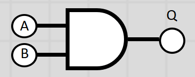
AND Gate
When using an AND gate, the only time the output will be high is if both of the inputs (A AND B) are high voltage (i.e. a 1). Writing a logic statement to represent this logic gate might look something like this:
Q = A AND B or Q = A.B
The dot (.) can be used to represent “AND”
here’s what a diagram of an AND gate looks like, as well as its truth table
Advertisement
Truth Tables
a truth table is a way of showing all possible outputs of a logic gate, or logic circuit. Each combination of inputs is used and the output is calculated using the rules of each gate.
Here is the truth table for an AND gate
| Input A | Input B | Output Q |
| 0 | 0 | 0 |
| 0 | 1 | 0 |
| 1 | 0 | 0 |
| 1 | 1 | 1 |
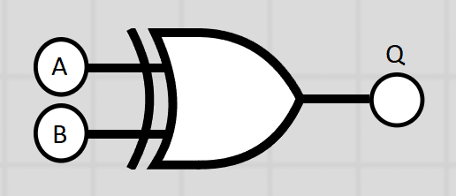
OR Gate
When using an OR gates, the output will be high only if input A or B is high. this means that the output will be a 1 if either A or B is 1. A logic statement might look like this:
Q = A OR B or Q = A+B
A cross (+) can denote the word “OR” in a logic statement.
Diagram
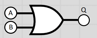
Truth Table
| Input A | Input B | Output Q |
| 0 | 0 | 0 |
| 0 | 1 | 1 |
| 1 | 0 | 1 |
| 1 | 1 | 1 |
NOT Gate
The NOT logic gate only has one input and will only output high voltage if the input is low voltage. This means Q will be 1 if A is 0. A logic statement could look like this:
Q = NOT A
Diagram
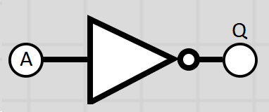
Truth Table
| Input A | Output Q |
| 0 | 1 |
| 1 | 0 |
With one input to the NOT gates, there are only 2 possible outcomes. It is always the opposite of the input.
As well as being able to produce a truth table it is also important in the GCSE Computer Science course and higher to recognise a logic gate by looking at a truth table. It is, therefore, necessary to learn the rules for each gate before we can begin to decipher what gate it may be as well as complete truth tables for larger, more complex logic circuits (more on that in another post). That’s all for now!
NAND Gate
Is a NOT-AND operation and is known as a NAND gate. Here we perform a NOT operation on an AND gate to get the opposite. The output is high voltage when both inputs are NOT 1. A logic statement might look like this:
Q = NOT(A AND B)
Gate
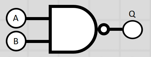
Truth Table
| Input A | Input B | Output Q |
| 0 | 0 | 1 |
| 0 | 1 | 1 |
| 1 | 0 | 1 |
| 1 | 1 | 0 |
NOR Gate
This is a NOT-OR operation. In this gate, the output will only be high if both inputs are NOT 1. A logic statement might look like this
Q = NOT(A OR B)
Diagram
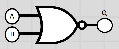
Truth Table
| Input A | Input B | Output Q |
| 0 | 0 | 1 |
| 0 | 1 | 0 |
| 1 | 0 | 0 |
| 1 | 1 | 0 |
XOR Gate
This is an Exclusive OR operation. In this gate, the output will only be high if either input is 1. If both inputs are 1 the output is 0, as well as if both inputs are 0. A logic statement might look like this:
Q = NOT(A OR B) or Q = A ⊕ B
Diagram
Truth Table
| Input A | Input B | Output Q |
| 0 | 0 | 0 |
| 0 | 1 | 1 |
| 1 | 0 | 1 |
| 1 | 1 | 0 |
Checkout my TES Shop for premium resources

Advertisement
miss u sir x
Comments are closed.